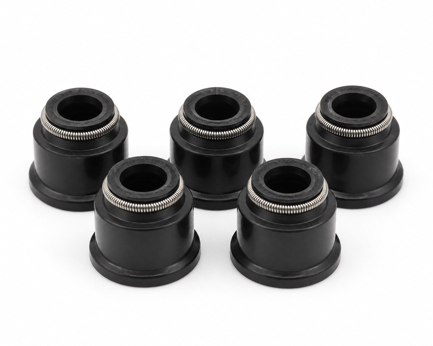
| Inner diameter (shaft diameter) |
The seal’s inner lip must seat on the actual shaft diameter with correct
interference — measured with a caliper, including any wear at the sealing
track. |
| Outer diameter (housing bore diameter) |
The outer case must fit the housing bore firmly enough to prevent spin-out and
leakage past the OD, without being impossible to install. |
| Seal width (axial thickness) |
The housing depth available for the seal sets the allowable width; an overly
wide or narrow seal seats badly and may leak. |
| Shaft speed and operating conditions |
Lip friction generates heat in proportion to speed; the lip profile and material
must suit the rpm the sealing point actually sees. |
| Operating temperature |
Continuous temperature at the seal — not just peak readings —
decides which compound family and grade will hold up over service life. |
| Oil type and additive compatibility |
Engine oils and their additive packages swell different compounds differently;
material compatibility must be verified against the oil actually used. |
| Shaft surface finish and hardness |
Where applicable, the shaft’s surface finish, hardness and absence of
wear grooves are as decisive as the seal itself — a new seal on a damaged
shaft will not last. |
| Pressure and direction of pressure exposure |
Conventional oil seals are designed for little or no pressure differential;
where pressure exists at the sealing point, the seal design must account for it. |
| Lip design and auxiliary features |
Single or double (dust) lip, garter spring, case construction and any auxiliary
features should match the original design intent for the position. |
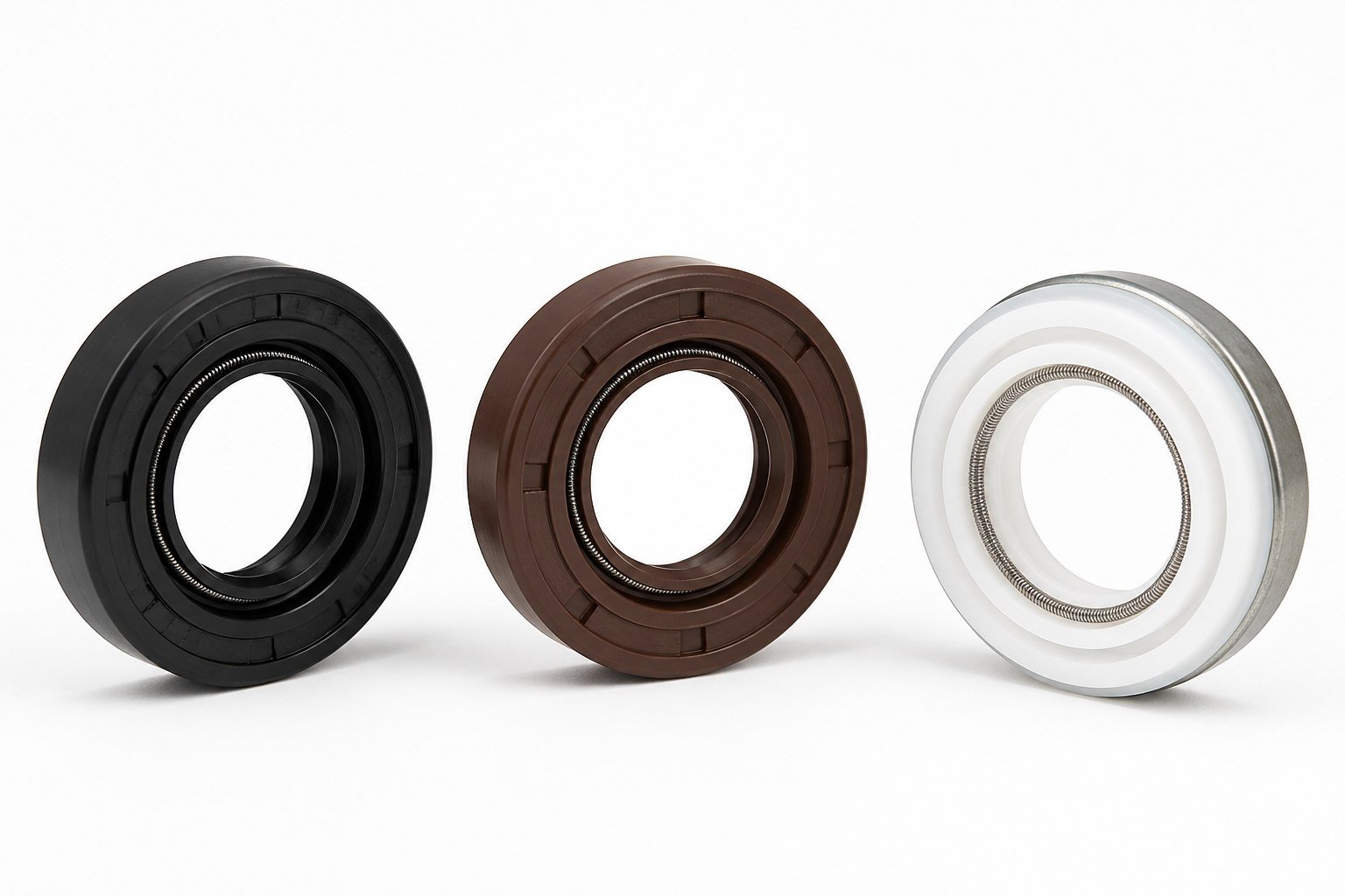
| Material or compound specification |
Identify the compound family (NBR, FKM, PTFE) and, where possible, the specific
grade rather than colour or brand name alone. |
| Installation constraints and tolerances |
Access, press-fit requirements, tooling and the dimensional tolerances of shaft
and bore all affect which seal designs can be installed correctly. |